
SHAPER MACHINE
Introduction:
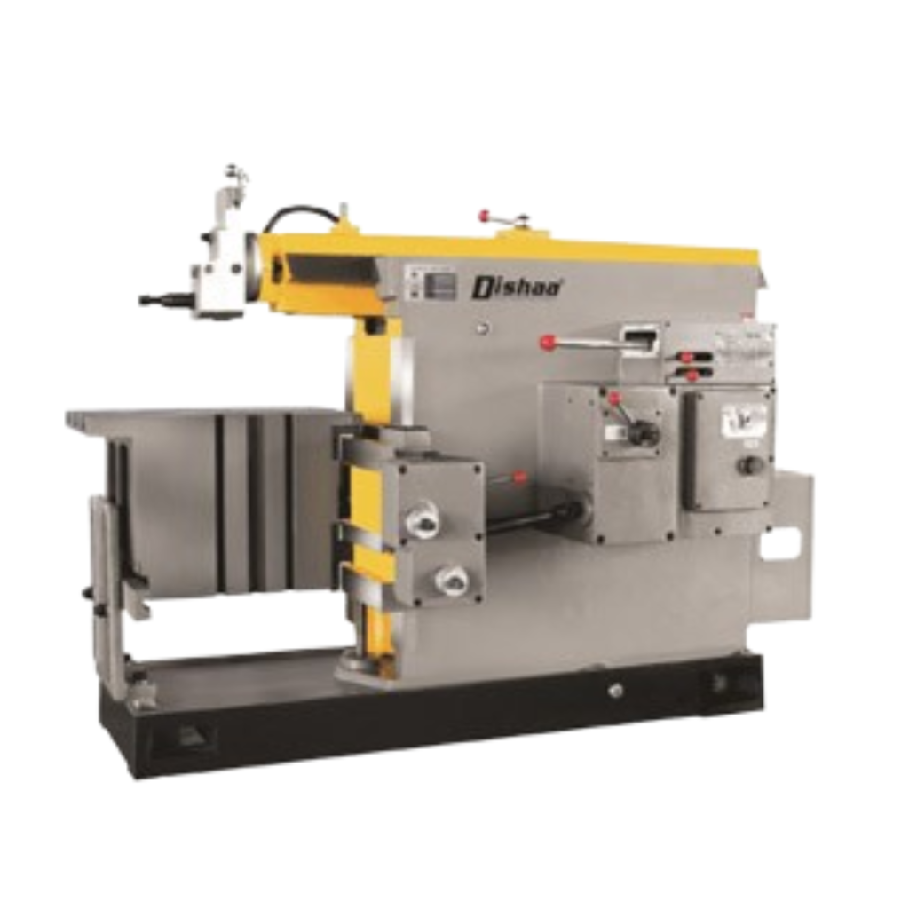
A Shaper Machine is a widely used mechanical tool in metalworking and fabrication industries designed to cut, shape, and finish metal surfaces with high precision. It belongs to the category of material-removing machines and is particularly known for producing flat, angular, and contoured surfaces. Unlike other machines such as milling or lathe machines, which rotate the cutting tool, a shaper machine moves the cutting tool linearly over the workpiece. This unique linear reciprocating motion enables precise removal of material, making it ideal for manufacturing components that require accurate dimensions and smooth finishes.
Shaper machines are versatile and are commonly used in workshops, industrial manufacturing, and engineering applications. They are suitable for shaping large and small workpieces alike, and their relatively simple mechanism makes them cost-effective for small to medium-scale production. Shapers are especially effective for cutting grooves, slots, keyways, and angular surfaces, as well as creating flat surfaces with uniform finish. Their ability to produce consistent results with minimal manual intervention has made them a mainstay in metal fabrication and mechanical workshops worldwide.
Working Principle of a Shaper Machine:
The basic working principle of a shaper machine involves a reciprocating movement of the cutting tool over the workpiece, which is held firmly on the machine table. The cutting tool removes material during the forward stroke, while the return stroke is typically idle. The linear motion is usually powered by an electric motor, flywheel, or mechanical linkage, ensuring smooth and controlled movement of the cutting tool. The workpiece can be fed manually or automatically for successive cuts, depending on the design of the shaper. Adjustable stroke length and cutting speed allow operators to work on a variety of materials, including mild steel, cast iron, and non-ferrous metals, with precision and efficiency.
Components of a Shaper Machine:
- Base – The foundation that supports the entire machine and absorbs vibrations.
- Column – Provides vertical support and houses the ram mechanism.
- Ram/Slide – The reciprocating part that carries the cutting tool.
- Table – A flat surface to hold the workpiece; may include adjustable mechanisms for height or angular movement.
- Tool Holder/Clamp – Holds the cutting tool securely in place.
- Crank Mechanism or Hydraulic Drive – Powers the reciprocating motion of the ram.
- Feed Mechanism – Moves the workpiece incrementally to allow successive cuts.
Applicatios:
- Cutting flat, angular, and contoured surfaces.
- Machining keyways, slots, and grooves in gears, pulleys, and shafts.
- Producing precise metal components for automotive, aerospace, and machinery industries.
- Removing excess material from rough-cast workpieces.
- Creating dies and molds in tool-making workshops.
Advantages:
- High precision and consistent output quality.
- Simple design with easy operation and maintenance.
- Ability to shape complex surfaces that may be difficult with other machines.
- Cost-effective for small to medium-scale production.
- Suitable for a variety of metals and alloys.
Features:
- Linear Tool Movement: Cuts in a straight-line motion using a single-point cutting tool.
- Adjustable Stroke Length: The stroke of the ram can be adjusted for different job sizes.
- Tool Head Adjustment: The tool post can be tilted or adjusted for various shaping angles.
- Automatic Feed Mechanism: Provides controlled feed to the workpiece.
In conclusion, the Shaper Machine is an essential tool in metalworking and industrial fabrication, providing reliable performance, versatility, and precision. Its linear reciprocating motion, simple mechanism, and adaptability make it ideal for a range of applications, from shaping flat surfaces to machining complex grooves and keyways. With proper use and maintenance, a shaper machine offers long-term efficiency, productivity, and consistent high-quality results
Technical Parameters:
| SPECIFICATIONS | Units | DMS635A | DMS6050 | DMS6063 | DMS6066 |
|---|---|---|---|---|---|
| Max. shaping length | mm | 350 | 500 | 630 | 660 |
| Table size | mm | 350*300 | 440*360 | 630*400 | 660*400 |
| Table horizontal travel (horizontal) | mm | 400 | 525 | 630 | 630 |
| Table vertical travel (vertical) | mm | 270 | 270 | 360 | 360 |
| Ram moving frequency per minute | times/min | 32-125 | 14-80 | 14-80 | 14-80 |
| Distance between ram lower end to table surface | mm | 330 | 370 | 385 | 385 |
| Tool head travel | mm | 110 | 120 | 120 | 120 |
| Tool head tilt angle | ° | ±60 | ±60 | ±60 | ±60 |
| Tool size | mm | 20*30 | 20*30 | 20*30 | 20*30 |
| mm | 14 | 18 | 18 | 18 | |
| Main motor power | kw | 1.5 | 3 | 3 | 3 |
| Machine weight | kg | 1250 | 1760 | 1870 | 1920 |
| Overall dimension | mm | 1500*1100*1500 | 2000*1300*1600 | 2000*1300*1650 | 2000*1300*1650 |